Print PDF version
 Code BiteSize
Revisions
|
Rev |
Details |
Date |
1
| Initial launch
| October 2023
|
Abbreviations
STFC
| Science and Technology Facilities Council
|
|---|
PSS
| Personnel Safety System
|
|---|
PPS
| Personnel Protection System |
|---|
SHE
| Safety Health and Environment
|
|---|
CNC
| Computerised Numerical Control
|
|---|
E/E/PE
| Electrical/Electronic/Programmable Electronic
|
|---|
IMP
| Interlock Management Plan
|
|---|
FSMP
| Functional Safety Management Plan
|
|---|
TUV
| Technical Inspection Association
|
|---|
SIL
| Safety Integrity Level
|
|---|
PL
| Performance Level
|
|---|
GRRA
| Grandfather Rights Risk Assessment
|
|---|
1. Purpose
1.1 This Document
This code details the STFC policy for the overall management of the lifecycle of mechanical and electrical interlocks for the protection of personnel and the environment to be applied throughout STFC. It considers current and developing best practice, of which current international standards are a core reference.
Compliance with this code is mandatory when applying interlocks as part of a risk reduction strategy.
1.2 Interlocks
An interlock system can be known by many names. Within STFC common terms used to describe such systems are interlocks, interlock systems, Personnel Safety Systems (PSS) and Personnel Protection Systems (PPS). These are used interchangeably within the organisation, however for the purpose of this code interlocks and interlock system will be used to describe implementations utilising either electrical, mechanical or a combination of both technologies.
Interlocks are widely used across STFC for protection against a range of hazards. These interlocks protect personnel, equipment and the environment as part of a risk reduction methodology. The implementation of such interlocks is achieved utilising either mechanical and/or electrical or electronic systems.
Such interlocks provide significant levels of risk reduction against injuries, ill health and environmental harm. They typically consist of sensors and logic functions that detect a dangerous condition and final elements, such as isolators or contactors that are manipulated to achieve a safe state. However, they can also consist of purely mechanical trapped key based systems that ensure hazards are removed prior to entry into the hazardous area.
The application of such purely mechanical interlocking systems is widespread within STFC. While the safe development and operation of such wholly mechanical systems can be achieved through the use of general good design practice, the policy, rules and procedures set out in this code will make this consistent across the implementation of interlocks within STFC.
1.3 Management of Interlocks
SHE Code 40 provides a framework for the management of the interlock lifecycle that will be employed by STFC to ensure STFC facilities are safe to use. This code should be read in conjunction with those STFC SHE codes for specific hazards where interlock control systems are frequently found such as laser, electricity, ionising radiation etc.
A risk assessment, as detailed in SHE Code 6 (Risk Management), must be undertaken prior to the application of this code, as it provides the essential requirements for the Interlock design.
2. Scope
2.1 Applicability
This code applies wherever interlocks are employed to mitigate the risk of harm to:
- People; or
- The Environment
This code applies to all staff, tenants, visitors, facility users and contractors at STFC sites.
The STFC sites house a wide variety of hazards where interlock systems may be employed as critical safety controls. These include, but are not limited to, those presented by the use of electricity, ionising radiation, lasers, oxygen depleted environments, explosive and flammable gases and dusts, cryogenic, radioactive and biological materials, electro-magnetic fields and moving mechanical equipment.
This code applies to the full interlock lifecycle on STFC facilities, equipment and experiments, where interlocks are employed., This includes, but is not limited to, the following functions, the: specification, design, fabrication, procurement, installation, testing, working on or near, commissioning, operation, modification, maintenance / repair, inspection, and decommissioning.
This code applies where STFC staff apply interlocks to equipment provided by STFC as part of international collaborations with third parties unless written agreement is obtained from the collaborator detailing their specific requirements, i.e. when equipment is supplied to other countries with different safety requirements. Care should, however, be taken to ensure that STFC is fulfilling all the necessary legislative requirements in the country of use as applicable.
Where third party equipment is integrated into STFC implemented interlocks, there will need to be collaboration between the supplier and STFC to ensure an appropriate system is designed and documented.
Equipment and STFC estate could also utilise the framework in this code to provide a structured approach to the implementation of the risk reduction strategy.
2.2 Exclusions
This code specifically excludes:
- Proprietary stand-alone equipment or machinery such as engineering equipment, for example, CNC milling machines or scientific equipment such as lasers that are employed as per manufacturer instructions and where the equipment safety functions are not integrated into the larger facility, i.e. an electric door with integrated collision detection is standalone, even if additional position monitoring switches are fitted as part of a wider interlock system or, a hydraulic system installation where additional e-stops are implemented into existing inputs as per the manufacturer’s instructions.
- Building Fire Alarm Systems, see
SHE Code 32: Fire Safety Management.
3. Interlocks Implementation
3.1 Introduction
This SHE code sets out the STFC policy for addressing the interlock lifecycle, alongside the codes that address individual hazards. The framework of this code gives focus on the interlocks aspects and the utilisation of interlocks to help manage risks identified by
SHE Code 6 (Risk Management).
Because of the range of hazards and local working practices across STFC, individual departments will need to develop their own procedures for implementing the overall framework set out in this code.
Triggers for invoking SHE Code 40 may arise from a variety of things ranging from the creation of a new facility through to a relatively minor modification to existing interlock systems. In all cases, all steps in the interlock lifecycle must be considered albeit some aspects may involve only a minor review of extant documentation to assure that there is no impact and/or that no changes are required.
3.2 Interlocks and the relationship to functional safety standards
The implementation of interlocks is a complex process that needs to ensure the system achieves adequate levels of risk reduction. Whether this is mechanical or electrical it still needs to follow an interlock lifecycle model to manage the process and ensure consistency between systems and across STFC in the management of safety.
The application of electrical interlocks is the subject of extensive and detailed guidance and standards, referred to as Functional Safety. The general benchmark of good practice is IEC 61508, Functional safety of electrical/electronic/programmable electronic safety related systems.
Functional Safety is the accepted term applied to the part of the overall safety of a system that depends on the correct functioning of electrical, electronic and programmable electronic (E/E/PE) safety related systems and other risk reduction measures . This would include any mechanical interlocks that contribute to the overall safety of such a system.
IEC 61508 has been used as the basis for industry specific standards for functional safety such as:
- IEC 61511: Functional safety – Safety instrumented systems for the process industry sector
- IEC 62061: Safety of machinery – Functional safety of safety-related control systems
Other standards exist that are also commonly used and accepted as best practice in industry such as:
- ISO 13849: Safety of machinery – Safety-related parts of control systems
As an extension to the implementation of functional safety, the use of the lifecycle model for the implementation of mechanical interlocks provides additional controls and consistency across the organisation.
3.3 Risk Assessment
This code does not detail the requirements associated with risk assessment and the determination of control measures required to reduce risks to an acceptable level.
SHE Code 40 assumes and requires that a Risk Assessment as per
SHE Code 6 (Risk Management) has been carried out for the STFC facility/system under consideration and that the following inputs are therefore available for that facility/system:
- The Concept
- The Overall Scope Definition
- A Hazard & Risk Analysis
- Overall Safety Requirements, to reduce risk to a level acceptable by STFC
A risk assessment identifies the controls in place to mitigate the risks identified, however it does not define the level of risk reduction that an interlock system is required to achieve as part of a risk reduction strategy. A critical step in the specification of an interlock system is this identification of the level of risk reduction that the interlock system must achieve.
A determination of the required risk reduction shall be carried out to identify the requirement for, and level of risk reduction required by, the interlock system.
There are a number of methods available to perform this. The chosen method will depend on the specifics of the system being assessed. Examples of methods are:
- Risk Graph (commonly used in ISO 13849)
- Matrix Assignment (commonly used in IEC 62061)
- Layer of Protection Analysis (commonly used in IEC 61511)
3.4 Interlocks Implementation
The implementation of interlocks requires consideration and planning of many aspects, covering a range of areas that are applicable throughout the lifecycle.
There are two ways to address the requirements for implementation of interlocks within STFC and therefore compliance with this code, either:
- a suitable recognised international standard that covers the lifecycle phases associated with, as a minimum, safety requirements allocation through to decommissioning:
- IEC 61508 (or sub-standards, i.e. IEC 62061, IEC 61511, etc.)
- ISO 13849 (With the addition of an Interlock Management Plan (IMP), see section 3.5)
- A process that affords equivalent to or better protection than that detailed within the recognised international standards applicable to interlocks lifecycle implementation.
The implementation of the interlock design lifecycle is addressed in the relevant international standards which are considered industry best practice. The departmental implementations of SC40 should be maintained in line with updates to the applicable international standards as new versions are released for use..
Any alternative approach is to be clearly defined and justified as to how it meets the requirement to point 2 above and will require the director of the department who owns and operates the equipment to sign off this implementation.
The key steps in the interlock lifecycle are:
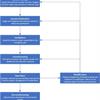
Click to open picture in new tab.
Within the overall implementation there are some key areas that need to be addressed as detailed in sections 3.5 to 3.8 below.
3.5 Interlock Management Plan
Key to the implementation of a consistent approach to interlocks is the generation of an interlock management plan (IMP), more commonly referred to as a Functional Safety Management Plan (FSMP). An IMP shall be produced to cover any work carried out on interlocks covered by this code through its lifecycle.
The purpose of an IMP is to ensure a clear and shared understanding of the approach to be used to achieve the required safety risk reduction using an interlock system. It does not need to exist as a separate document; for example it could be included in wider safety management plans or engineering management plans. The IMP should be produced by drawing on standard organisational/department practices/procedures where available, e.g. Safety Management System.
The IMP should be updated at a frequency agreed by key stakeholders, but it would be unusual if the IMP were not reviewed at least on major project events, e.g. Major life-cycle phase reviews.
Some key elements that must be included are:
- The activities to be carried out as part of the lifecycle and the persons responsible for carrying out and reviewing these
- The overall policy, strategy, procedures and resources that will ensure the functional safety requirements can be fulfilled and relevant information recorded and maintained
- The strategy for configuration management and management of change
- The verification and validation plan throughout the lifecycle
Refer to the IEC 61508 suite of standards for a clear definition of the full content requirements of the IMP.
3.6 Change Management
Given the lifespan of facilities within the STFC, changes to the systems providing risk reduction are inevitable and need to be managed effectively and efficiently to provide a level of risk that remains acceptable.
The management of change to interlocks should follow STFC standards where available. There is nothing unique to interlocks in this respect. However, where STFC Standards do not exist, Departments should develop and follow their own procedures for implementing Change Management.
3.7 Legacy Interlocks
It has been accepted that, with the adoption of SHE Code 40, all new interlock installations from concept to disposal will comply with the new code.
It is key however that all systems to which this code would apply are known and managed appropriately. Departments shall hold a record of all such systems that are within their control.
Existing (‘legacy’) installations will benefit from so called grandfather rights. A grandfather clause (or grandfather policy or grandfathering) is a provision in which an old rule continues to apply to some existing situations while a new rule will apply to all future cases.
This would normally continue to apply until:
- A risk assessment under
SHE Code 6 (Risk Management) identifies a risk that needs to be further reduced to become acceptable, or to conform to good practice, and the chosen method of risk control includes E/E/PE equipment; or
- Existing/legacy installations where survey/assessment shows significant dependence on E/E/PE for personnel protection – to be applied on a priority call and in timescale dictated by STFC and Departmental review.
Frequently, the exemption is limited; it may extend for a set time, or it may be lost under certain circumstances.
Legacy systems are to be defined as systems that have a completed design finalised for installation, and are within the installation, commissioning, operational or decommissioning phases of their project lifecycle by 31st January 2026. Systems still within the design phase after this time will not be considered legacy and shall comply with this code.
By 31st January 2026 these legacy systems shall be identified, and a suitable and sufficient assessment will have been carried out for each system to justify its continued use. Additional guidance on the expectations of the grandfather rights risk assessment (GRRA) can be found in
Appendix B.
There is no prescribed time that will apply to grandfather rights for legacy interlocks. It will be up to department directors to decide if any grandfather rights shall be time limited.
Circumstances that may result in the loss of grandfather rights would include, for example, modification of the interlocks to change its functionality. This may be influenced by the degree of changes being made. It will be up to departments to determine the criteria that will result in the loss of grandfather rights. Additional guidance providing some of the expected criteria that would trigger an upgrade can be found in
Appendix B.
Existing (legacy) interlocks may not be fully documented as required by SHE Code 40. In these cases, where the need for review or change has been triggered, it would be necessary to identify, log and review the available information. This could include not only formal written records but also the informal knowledge of those involved in the development and operation of the interlock system. This understanding should be explicitly documented and subjected to appropriate review as part of a formal Change Management process.
3.8 Mechanical Interlocks
General Approach
The implementation of mechanical interlocking systems either standalone or as part of a functional safety system, referring primarily to trapped key based systems, e.g. Castell or Fortress keys, shall follow the implementation approach detailed within this code. Although the application of a trapped key interlocking philosophy is not covered by the functional safety standards unless it forms a layer of protection in a wider E/E/PE based implementation, this best practice is considered appropriate.
As part of this approach the applicable documentation, reviews and change management should be implemented.
Key Register
A register of all trapped key reference numbers for STFC sites is held by the SHE Group, accessed via the SHE website. This is to ensure that duplicate key references are not utilised by a single STFC department.
All new proposed key references/numbers should be registered with SHE Group
PRIOR to being ordered to ensure that they are unique to that department and recorded.
Failure to ensure that all keys on a site are unique could result in a safety system being compromised by the use of a duplicate key.
The key register is located at
this site.
Additional Information
There is additional information on the design and application of trapped key interlocking devices in ISO/TS 19837:2018
4. Responsibilities
4.1 Introduction:
-
4.1.1 The competencies and level of experience required to undertake these roles within the interlocks lifecycle will vary and will depend on the nature of the hazards, operational environment and complexity of the risk control measures required. It is the responsibility of the department to tailor the competency required of these roles to be appropriate to the situation at hand.
-
-
4.1.2 Persons carrying out roles within the Interlocks lifecycle are expected to be competent and appropriately trained for the role. Refer to Appendix A for training requirements.
-
-
4.1.3 The management process employed within this code is a Matrix management approach, where the persons who manage competence are not necessarily the same as those that manage systems or permit work on such systems. This approach is proposed to maintain a simple and scalable implementation.
-
- Note that these roles may not map directly to existing STFC jobs.
4.2 Directors whose operations include equipment/facilities employing interlock systems shall:
-
4.2.1 Approve in writing any deviations from the application of international standards (as per point 2 in Section 3.4) for their department and ensure that this decision is reviewed on a periodic basis.
-
-
4.2.2 Approve in writing the continued operation of any legacy systems as part of a grandfather rights methodology for the department (see Appendix B for additional guidance).
-
-
4.2.3 Ensure that the specification, design, fabrication, procurement, installation, testing, commissioning, operation, modification, maintenance / repair, inspection and decommissioning of interlock systems meet requirements of this code throughout the interlock system lifecycle, see
section 3.
-
-
4.2.4 Ensure a sufficient number of competent people are identified and that sufficient resource and facilities are available to them to implement the requirement of this code throughout the interlock system lifecycle, see
section 3. See
Appendix A for training and competence requirements. Where necessary, collaborate with or share such specialist personnel with other Departments.
-
-
4.2.5 Ensure the exact extent of the interlock systems and installations for which a person working on interlock systems is responsible is identified and documented, maintaining clear demarcation between areas.
-
-
4.2.6 Ensure that all reported SHE incidents involving interlocks within their area of responsibility are investigated. Where learning points can be derived, identify suitable persons to work with SHE Group to ensure that the learning is cascaded to persons working on interlock systems and to the wider STFC interlocks community.
4.3 Managers of equipment/facilities employing interlock systems, including Contract Supervising Officers shall:
-
4.3.1 Be accountable for the safe operation of their equipment and ensuring that only competent persons are permitted to work on the interlock systems that they manage.
-
-
4.3.2 Ensure appropriate implementation, administration and monitoring of the application of this SHE code is carried out for the systems for which they are responsible.
-
-
4.3.3 Prior to allowing work on their equipment/facilities that contain interlocks as a control measure ensure that a risk assessment and method statement for the work planned has been established, see
SHE Code 6 (Risk Management) based on the advice of competent individuals, see Appendix A for training and competence requirements, on all aspects of the interlock system lifecycle.
-
-
4.3.4 Where such work is undertaken by STFC staff, or contractors working on their behalf, the competence of all individuals working on or near interlock systems must be approved before undertaking work or tests, see
Appendix A for training and competence requirements. Maintain appropriate records to show that personnel carrying out work on interlock system are competent and appropriately trained.
-
-
4.3.5 Ensure all Persons working with/on Interlock systems are made aware of any relevant safety information, defect report or operational restriction on the functional systems or equipment on which they are working as soon as is reasonably practicable, providing appropriate advice to prevent injury.
-
-
4.3.6 Consult with the competent individuals prior to purchasing or embarking on a new project in which interlock may be required as a risk reduction measure.
-
-
4.3.7 Instigate the change management process when required and ensure that appropriate persons are carrying out the required modifications to systems under their control.
-
-
4.3.8 When dismantling/decommissioning/disposing of equipment that has interlocks they must consult competent individuals.
-
-
4.3.9 Ensure that when facility users/visitors bring their own, non-proprietary, equipment into the STFC sites/facilities containing interlocks they must consult competent individuals for assurance that such equipment meets the requirements of this SHE Code.
-
-
4.3.10 Ensure that all incidents, near misses, hazardous conditions, dangerous occurrences or failures of safe systems of work for staff and others working on or using interlocks, including contractors, are reported through
Evotix Assure following
SHE Code 5 (Incident Reporting and Investigation).
4.4 Staff, tenants, contractors, facility users or visitors shall:
-
4.4.1 Report all interlock incidents or near misses to the Equipment Manager as soon as is practicable, and in
Evotix Assure following
SHE Code 5 (Incident Reporting and Investigation).
-
-
4.4.2 Only use interlock systems on which they have been suitably trained and deemed competent.
-
-
4.2.3 Use interlock systems as demonstrated and instructed, and as per any supplied manuals. Where there is ambiguity or uncertainly then a competent person should be sort to clarity these items before continuing operation of the interlock system.
4.5 SHE Group shall:
-
4.5.1 Ensure STFC subscribes to suitable industry fora where serious interlock incidents, equipment faults/failures and manufacturers advisory notices are published sharing relevant information across STFC in a timely manner.
-
-
4.5.2 Ensure that learning from interlock SHE incidents and good practices are shared across STFC.
-
-
4.5.3 Manage the trapped key interlock database.
4.6 Line managers/mnagers of persons working on interlock systems shall:
-
4.6.1 Identify and maintain, in writing and record, the completed training and competence for the relevant lifecycle phases (see
Appendix A), of persons under their management working on interlock systems.
-
-
4.6.2 Review the training and competence of persons working on interlock systems at least every 5 years or more frequently depending on performance and if necessary suspend their involvement in interlock activities documenting the reasons why. The equipment manager is to be advised of such action and the corrective action recommended, in collaboration with a competent person, ensuring the continued safe operation of the safety related systems and installations.
-
-
4.6.3 Ensure that all incidents, near misses, hazardous conditions, dangerous occurrences or failures of safe systems of work are promptly reported by the relevant example Persons working on interlock systems and others undertaking interlock related work, including contractors through
Evotix Assure following
SHE Code 5 (Incident Reporting and Investigation).
4.7 Personnel involved in the interlock lifecycle shall:
-
4.7.1 The Interlock lifecycle can be significant durations (>30 years), span an extremely large scope, and roles and responsibilities within it will vary between and within both departments and projects.
-
-
4.7.2These roles and responsibilities, and named individuals assigned to these, shall be documented by departments as part of the IMP for the facility, project or equipment as applicable.
-
-
4.7.3 Roles and responsibilities within the interlock lifecycle shall include the following:
-
System Manager/Owner - responsibilities such as co-ordinating effort to establish the overarching needs of the system and ensuring formal documentation is generated as required, including the generation and maintaining of the IMP. Responsible for the instigation of the change management procedure during the operational phase of the interlock system. The responsibilities of this person/role will potentially change during the lifecycle of the project depending on the lifecycle phase requirements.
-
Design – covers all levels of design from concept through to detailed design. Responsible for producing system requirements & specifications, functional design of the system including (if applicable) software, wiring, etc. and all relevant documentation as dictated by the IMP.
-
Testing and Commissioning - responsible for commissioning and testing of the functional safety as well as physical testing of the overall installation against the initial aims and requirements of the system.
-
Operation – the user of the system who is responsible for using it in a safe and appropriate manner. Such users may have responsibility for training and supervising others in the use of the system.
-
Maintenance and Repair - responsible for the ongoing maintenance and repair of systems, ensuring no work is undertaken without authorisation of the manager/system owner.
-
-
4.7.4 Where roles within the lifecycle are undertaken by committees, memberships of such shall be clearly defined in the IMP.
-
-
Regardless of their role personnel involved in the interlock lifecycle shall:
-
-
4.7.5 Be responsible for the practical implementation and operation of this SHE Code for the tasks and activities for which they are responsible.
-
-
4.7.6 Ensure that the interlock systems under their responsibility have all required accurate documentation available, including drawings / schematics, so that the interlock system can be operated, modified, maintained and decommissioned safely. All changes to the interlock system shall be recorded.
-
-
4.7.7 Ensure that all incidents, near misses, hazardous conditions, dangerous occurrences or failures of safe systems of work are promptly reported by the relevant example Persons working on interlock systems and others undertaking work in the interlock lifecycle, including contractors through
Evotix Assure following
SHE Code 5 (Incident Reporting and Investigation).
-
-
4.7.8 Instruct persons required to operate interlock system equipment under their control in the safe use of that equipment and advise on the hazards arising from improper operation.